欢迎来到颐乐智能家居官网!
18025871331
中文
EN
关于我们ABOUT US
Electromagnetic compatibility (EMC) basics summary
发布时间:2022-04-07
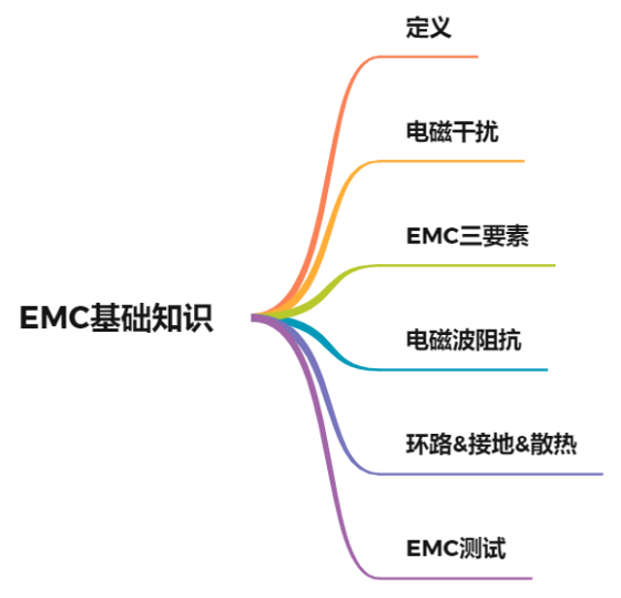
Mind map of this paper:
01
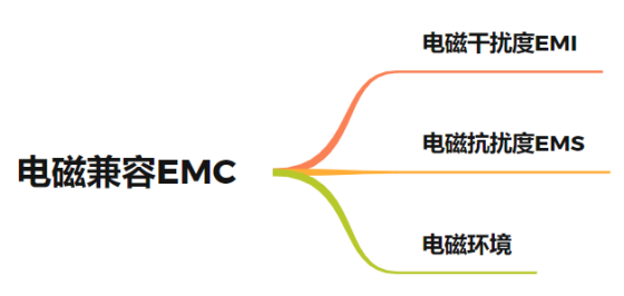
EMC (electro magnetic compatibility) means that the electronic and electrical equipment or system will not cause performance degradation, function loss or damage due to the surrounding electromagnetic environment in the expected electromagnetic environment, and will not generate excessive electromagnetic energy in the surrounding environment, so as to affect the normal operation of the surrounding equipment.
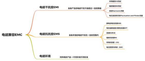
EMI (electro magnetic interference): the electromagnetic interference generated by itself cannot exceed a certain limit.
EMS (electro magnetic immunity): the electromagnetic interference borne by itself is within a certain range.
Electromagnetic environment: for the same kind of products, different environments have different standards.
It should be noted that the above is based on one premise: in a certain environment, the equipment or system is in normal operation.
02
Cause of electromagnetic interference: unnecessary part of voltage / current change.
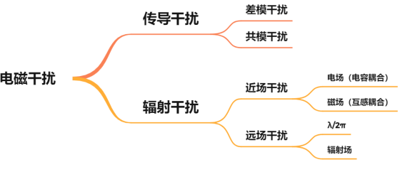
There are two coupling ways of electromagnetic interference: conductor conduction and space radiation.
The reason for conductor conduction interference is that the current always follows the "minimum impedance" path. Take the shielded wire as an example. At low frequency (f < 1kHz), the resistance of the wire plays a major role, and most of the current flows through the copper wire of the wire; When the impedance of the high-frequency shielding layer is > 10kHz, the current flowing through the high-frequency shielding layer is less than 10kHz.
There are two ways to transmit interference current on the wire: common mode and differential mode.
Generally, the useful signal is differential mode signal, so the common mode current can interfere with the useful signal only when it is transformed into differential mode current. Impedance balance prevents the common mode current from changing to differential mode. Multi point grounding can be used to reduce the common impedance of the ground wire and reduce the impedance interference of the common ground wire.
Space radiated interference is divided into near-field and far-field.
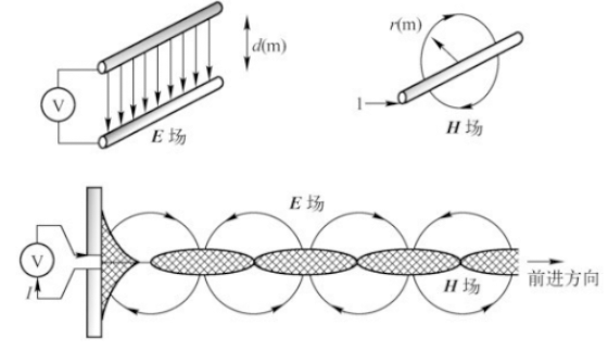
Near field, also known as inductive field, is closely related to the nature of field source.
When the field source is high voltage and small current, it is mainly electric field;
When the field source is low voltage and high current, it is mainly represented by magnetic field.
Whether electric or magnetic field, when the distance is greater than λ/ 2 π becomes the far field.
Far field is also called radiation field. The far field belongs to plane wave, which is easy to analyze and measure, while the near field has the problem of mutual conversion between electric field and magnetic field, which is more complex.
The problem here is that if the wire becomes an antenna, sometimes it is difficult to distinguish whether it is conducted interference or radiated interference?
Conducted interference is the main interference in the low frequency band, especially below 30 MHz. Or it can be estimated that when the length of equipment and wires is shorter than the wavelength, the main problem is conducted interference. When their size is longer than the wavelength, the main problem is radiated interference.
The interference signal radiates electromagnetic energy outward in the form of plane electromagnetic wave, and then enters the disturbed line, equipment or system through the coupling of common impedance in the form of leakage and coupling through the medium of insulating support (including air).
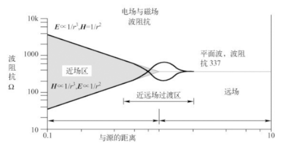
For example: 900MHz, the turning point of plane wave is 50mm
There are two necessary conditions for electromagnetic wave radiation: changing voltage / current and radiating antenna. Without one of them, there will be no large amount of radiation interference.
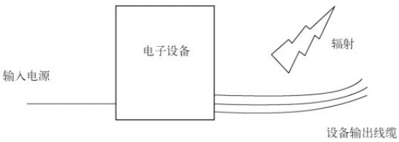
Some data will give the concept of transient interference, as the name suggests: electromagnetic interference with short time but large amplitude. Transient interference generally refers to all kinds of electrical fast pulse transients (EFT), all kinds of surges (surge) and electrostatic discharge (ESD).
03
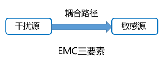
Key point: eliminating any one of these factors can meet the requirements of EMC design.
Cutting off the coupling path is the most effective EMC treatment measure.
Understand the following propagation paths:
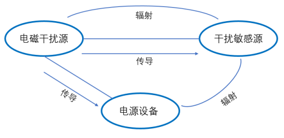
Electromagnetic interference can be conducted interference transmitted through power line, signal line, ground wire, earth and other channels, as well as space radiation interference directly transmitted through space. These interferences or noises do not exist independently, and new complex noises will appear in the propagation process. The superposition problem of this problem is the difficulty to solve the problem.
04
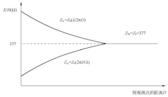
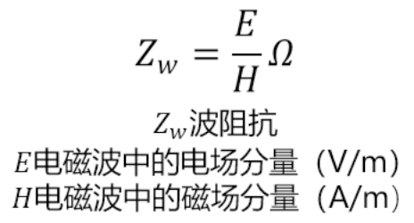
In the near-field region, the wave impedance is related to the position, impedance and frequency of the radiation source and the medium around the radiation source; In the far-field region, the wave impedance is equal to the characteristic impedance of the electromagnetic wave propagation medium; In vacuum, the wave impedance is 377 Ω.
From 377 Ω to the characteristic impedance of free space:

There is a basic concept to talk about: the difference between dB and DBM. It is often mentioned before dB. DBM is the value of power relative to 1 MW.
As for the difference, the above formula is more direct:


05
环路
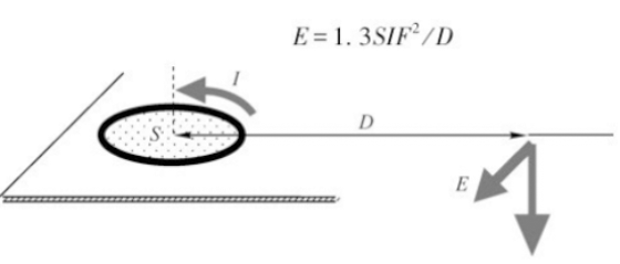

The loop formed by current in the transmission path and return path is one of the reasons for PCB radiation emission.
There is a loop for the transmission of any signal in electronic products. If the signal is alternating, the loop where the signal is located will generate radiation. When the current and frequency of the signal in the product are determined, the radiation intensity generated by the signal loop is related to the loop area. Controlling the area of the signal loop can control the EMC problem.
Single point & multipoint grounding
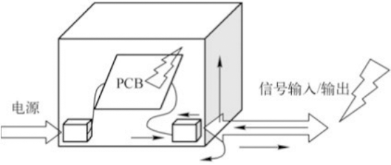
Whether single point grounding is selected for electronic equipment mainly depends on the working signal frequency of the system and the length of the grounding wire, that is, its characterization quantity L/ λ。 L/ λ<= 0.1, select single point grounding. The application range of single point grounding is generally below 300kHz, and it can also be below 1MHz in some occasions.
When the length of the ground wire is odd times of 1 / 4 wavelength, the impedance of the ground wire becomes very high, resulting in antenna effect, that is, the ground wire radiates noise signals outward like an antenna. If one point grounding is used, the length of the ground wire shall not exceed 1 / 20 of the wavelength, otherwise multi-point grounding shall be used.
Heat dissipation & shielding
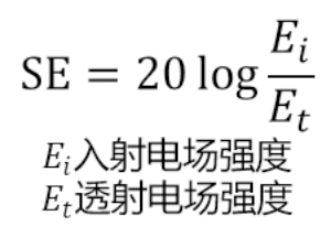

Shielding and heat dissipation are contradictory. The heat dissipation hole is generally a group of holes. Forced convection is carried out by the fan. These holes will cause electromagnetic leakage and reduce the shielding effect. The larger the hole, the worse the shielding effect. Usually, the shell of the system is equipped with cooling holes, which will affect the shielding performance of the whole system.
06
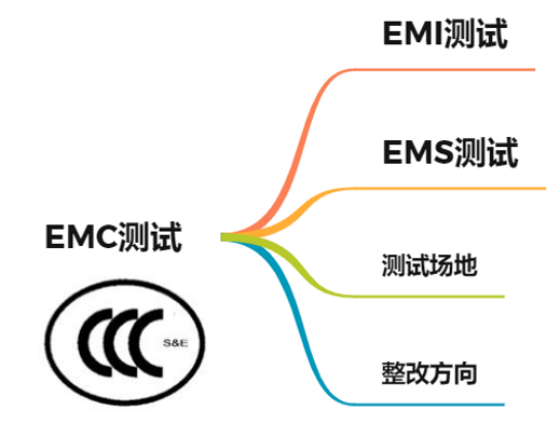
EMC testing can be divided into two categories:
One is electromagnetic interference (EMI) test, which tests the interference emission of electronic product system to other equipment and electromagnetic space.
One is electromagnetic immunity (EMS) test, which tests the ability of electronic equipment to resist space electromagnetic interference.
There are 2 EMI test items in national standards, 7 EMI test items in military standards, 10 EMS test items and 12 Military guaranteed EMS test items.
It's easy to understand that there are different requirements for different industries. The problem is that EMC testing has different standards, and each industry will refine according to the standards to determine the level and requirements they meet.
EMI test items:
① Conducted disturbance (CE) test (power line, signal line, control line)
② Radiation disturbance (RE) test
③ Harmonic measurement
④ Voltage fluctuation and flicker measurement
EMS test items:
① Electrostatic discharge immunity (ESD)
② Electrical fast transient burst immunity (EFT)
③ Surge
④ Radiated Immunity (RS)
⑤ Conducted immunity (CS)
⑥ Voltage sags and interruptions (DIP)
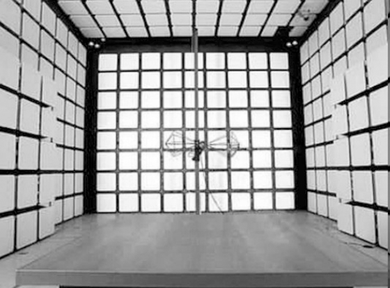
EMI test sites include semi anechoic chamber, full anechoic chamber and open field.
Product related EMC test is necessary. If there are problems in product EMC test, the rectification direction is as follows:
1. Electrostatic immunity test - > shielding
2. Electrical fast transient burst immunity test power isolation, use shielded twisted pair & install magnetic ring.
3. Install surge suppressor for surge (impact) immunity test
4. Immunity test of conducted disturbance induced by RF field shielding, grounding and filtering
5. Radio frequency electromagnetic field radiation immunity test: the conductive foam compresses the cable to keep the minimum gap.
6. Conduct and transmit power isolation, filtering, grounding and reduce loop area.
7. If the radiation emission exceeds the standard, shield the grounding, check the connection, install the magnetic ring, and check the simulation equipment.
07
The EMC design of products must pass the overall design, from circuit design to component selection, from PCB plate making to prototype debugging, from the test of electronic equipment to release, and the possible EMC problems must be considered in every step. From the initial planning of products to the end of final certification, the EMC design idea must be integrated in every step, so as to truly control the EMC problems.


 关注公众号
关注公众号